Thursday 25 August 2022

New Homes to Have Charge Points for Electric Vehicles as Standard


Housebuilders in England will soon be fitting EV chargers to new homes, how do the new rules work and what is happening in the other home nations?

How the New Rules Work in England

In December 2021, the government published Approved Document S, a new part of the Building Regulations that apply in England.  The new regulations require developers to fit Electric Vehicle (EV) charging points when building a new home.

Where a new residential building has a parking space then EV charge points must be provided - one per dwelling or one per parking space, whichever is the lower.

So for a new house that has its own parking space at least one EV charger must be installed.

For an apartment block with a car park for residents the number of EV chargers provided would be the number of dwellings in the block, (unless the number of spaces in the car park was less than the number of dwellings).

Exemptions exist if the developer can demonstrate that fitting so many EV chargers would overload the electricity supply.  If grid reinforcement costs exceed £3,600 per charge point then the developer can install less EV charging - up to the number that would cause grid reinforcement costs to exceed £3,600 (excluding VAT) per charge point.  Any unserved parking spaces must instead be provided with a cable route from the power supply to the parking space to aid future installation (but not a cable).

Each electric vehicle charge point needs to have a minimum nominal rated output of 7kW, be untethered (have a socket rather than a lead), and have an indicator to show the equipment’s charging status.

The approved document took effect on 15 June 2022. It does not apply to new buildings submitted for planning before that date, unless the plot build starts after 15 June 2023. 

What this means in practice is that any new building sites where planning permission was applied for after June 2022 will need to meet the new requirements.  Building sites that had already applied for planning permission before June 2022 will need to transition individual plots to meet the new regulations if these start being built after June 2023.


New Rules in Scotland are Coming Soon

The Scottish Government has announced that it will legislate  before the end of 2022 to ensure developers provide electric vehicle (EV) charge points in the construction of new residential and non-residential buildings.  All new homes, including flats, with a dedicated car parking space are built with an electric charge point.

The details are outlined in the consultation response:

All new dwellings with a parking space are to have at least one EV charge point socket with minimum 7kW output power rating.  There is an exemption to requirement to install EV charge point if additional cost of electricity grid connection exceeds £2,000.  If exemption applies ducting infrastructure to be installed in each car parking space.


Wales 

An EV Charging Strategy for Wales published March 2021 proposes that new homes should be 'ready' for an EV charger - suggesting only cable provision, though this position looks weak compared to the positions taken by England and Scotland and I'd expect Wales to follow England and Scotland and require actual chargers are installed with an exemption if grid reinforcement costs are prohibitive.


Northern Ireland 

An EV Infrastructure Task-Force has been created to develop an EV Infrastructure Action Plan.  It's first meeting was December 2021.  Don't hold your breath on this one.


Friday 15 July 2022

New Building Regulations for Scotland


In June 2022 the Scottish Government published its consultation response on changes to further tighten the Building Regulations for energy efficiency.  New developments in Scotland seeking a Building Warrant after 1 December 2022, will need to meet the new regulations.

Although most respondents to the consultation were in support of a higher performance target (delivering a 57% reduction in CO2 emissions), the government instead opted for the lower performance target which is expected to reduce the CO2 emissions of new homes in Scotland by 32%.

The central element of the building regulations for energy is the so-called 'Notional House Specification' which defines the target that a developer must meet. (For a full explanation of how the Notional House Specification works see this earlier blog).

The 2022 Building Regulations in Scotland gives three Notional House Specifications - one for homes heated with a heat pump, another for homes heated by a heat network and a third based on mains gas  for homes using any other heating systems.

The table below contrasts key elements of the new Notional House Specification with those in the previous version of Scottish Building Regulations and also with the new regulations that came into force in England this year.


As can be seen, the new Scottish Building regulations require a significant improvement in U-values (insulation) and airtightness compared to the current (2015) regulations.  They also come in slightly better than the latest regulations for England (it would have been a major surprise if they didn't!)

Of interest to solar industry participants will be the increase of PV provision in the gas heated notional house compared to the 2015 regulations.  

In 2015 Scotland became the first of the nations to add solar PV to the notional house - the amount asked for was the dwelling total floor area in m2 x 0.01kWp, which corresponds to 20Wp of solar per 1m2 of ground floor area (for a two storey building of equal ground and first floor areas).  The new requirement is for 0.4 x ground floor area in m2 / 6.5 -  which works out to be 62Wp of solar per 1m2 of ground floor area - around 3 times more solar per house.


Other Changes


Scottish Goverment also changed the way the benefits from solar are taken into account in the calculation.  The energy and carbon benefit of on-site generation is capped at the level assessed as being used on site (excluding the energy exported the grid).  This change is likely to incentivise the use of technologies to store excess solar energy for later use - for example battery storage or energy diverters that heat hot water with excess solar energy.


Good News for Solar?


The new regulations look like great news for solar in Scotland.  The Building Regulations are 'solution neutral' allowing developers to choose a combination of heating system, insulation and on-site generation that equals or exceeds the performance of the Notional House Specification.  Since both developers and house buyers prefer gas boilers to heat pumps, this regulation change is likely to increase the amount of solar installed on new homes in Scotland because of the three-fold increase in panel power in the specification.

However, the cloud on the horizon for the solar industry is another piece of legislation - the New Build Heating Standard, which will remove the gas boiler option for housebuilders by banning their use in new homes.  

Under these Building Regulations, once a housebuilder is forced to use heat pumps, the requirement for solar drops away because the Notional House Specification for heat pump heated homes does not include it.

Solar PV and heat pumps are a great match, with solar offsetting higher running costs of heat pumps - why would Scottish Government have no solar on the heat pump specification?  It all boils down to the cost for the developer - the regulations have been set up to encourage housebuilders to consider heat pumps before the 2024 regulations, and the notional house has been set up to try to level the playing field for build costs - leaving waste water heat recovery and solar off the heat pump specification.

No heed has been paid to the increased running costs the home owner will suffer in a heat pump heated home compared to a home with a gas boiler and solar PV.

Once there is a regulatory requirement in place to use a heat pump, then then the incentive to try to lower the cost of a heat pump installation versus gas plus solar falls away.  Scottish Government should commit to review the building regulations at the same time as bringing in its New Build Heat Standard to require solar PV on heat pump heated homes too.  This way it will ensure a just energy transition and reduce the risk of a consumer rejection of heat pumps.

Monday 30 May 2022

On The Causes of Solar Fires


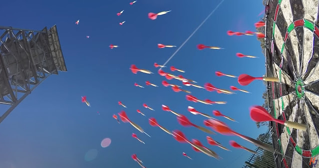
Longest Distance Darts Bullseye World Record Attempt (youtube video


If you're looking to break the record for the longest distance bullseye on a dartboard how do you do it?  You throw lots of darts.

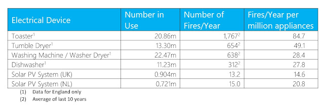
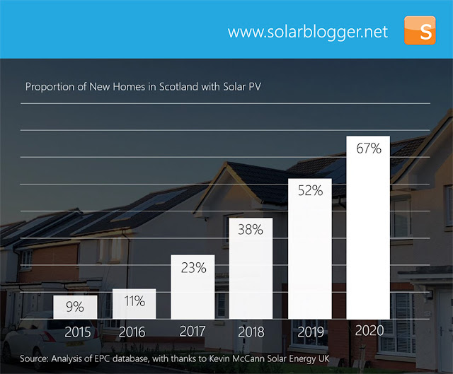
Solar is a very safe technology.  It's less dangerous than a toaster or a tumble dryer (see my earlier blog putting solar risks into context).  But just like when trying to hit the bullseye, the more solar that is installed, the greater is the chance that low-probability, high-consequence events like solar fires occur.  

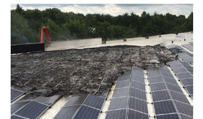
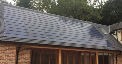
But fires have already been happening and, as the examples below show, they occur in all types of installation - rack-mounted above pitched roofs, flat roof installations and roof integrated BIPV, and unlike a toaster, solar PV is often spread over and through the building, so the outcome of a solar fire can be very significant.

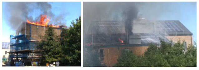
Rack mounted above roof solar, 2017, Bow Wharf, Bethnal Green, London


Flat roof solar, 2016, Denekamp, Utrecht, Netherlands


Roof integrated solar, 2018, Vinkeveen, Netherlands

Insurance companies are becoming more and more aware of the risks of solar fires and if the solar industry wants to avoid having impractical or poorly thought through 'solutions' imposed upon it, then we need to collectively do more to improve the safety of the solar systems we design and install.

Back in the early 1960s many people wouldn't have thought twice about jumping into a car with a few glasses of beer on board - a legal drink drive limit didn't come into force in the UK until 1967.   Nor would they worry about speeding off without the benefits of driver, passenger and side air bags, side impact protection bars, or an anti lock braking system to keep them safe.  Although the car would probably be equipped with a 3-point seatbelt (they were invented in 1959) there was no legal requirement to use it and many people didn't.  

Safety is constantly improving.  Risks people were once happy to accept now seem unthinkable in from the vantage point of today.

In this blog we're going to take a look at two recent research studies that have advanced understanding of the causes of solar PV fires and try to answer the questions "what components are most likely to be the source of fire, and what can be done to improve the fire safety of solar installations?"  


Solar Fire Research 


BRE Solar Fire Study


Researchers from the Building Research Establishment (BRE) investigated 80 fires in the UK that involved solar PV systems in some way, either because it was a potential source of the fire or because it was involved in a fire that started elsewhere. (Link to report here).

The solar PV system was found to be the source of the fire in 56 of the incidents.   Of these 22 were serious fires (that were difficult to extinguish and spread beyond the point of origination), with the remainder being classified as localized or ‘thermal events’ (smoking, overheating).


  • Between 26 and 28 of these were linked to the DC isolator (43% of fires)
  • Between 6 and 11 to the DC cables and connectors (17% of fires)
  • 6-9 at the inverter (14% of fires) and
  • 2-5 in the module.

No information is given in the report on which causes of fire were more likely to result in serious fires.  Correspondence with one of the authors of the report on this question clarified that it wasn't recorded and that the numbers were likely to be too small to draw a conclusion in any case.


TNO Solar Fire Study

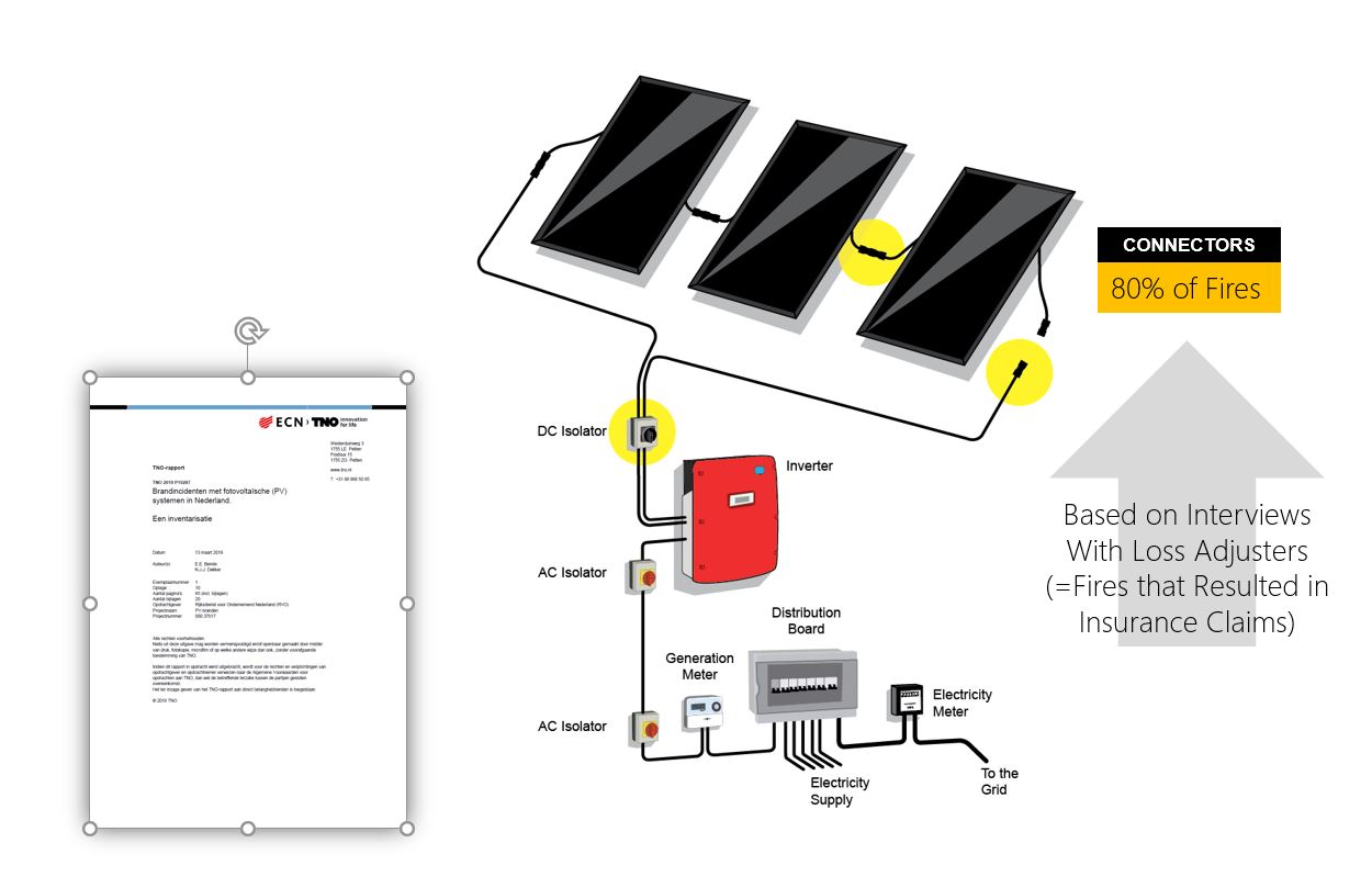
This report by Dutch researchers at TNO was written in response to a number of solar fires in the Netherlands during 2018 that made the news in local media.  Unlike the UK research which visited sites and collected physical evidence, the TNO project was limited  to compiling a register of incidents and interviewing residents, damage experts, fire service staff and solar installers.  The available budget did not reach to in-depth analysis or forensic examination of fires.  (Link to report here).


According to the TNO study of solar fires in Netherlands, more than 80% of incidents investigated started with the DC connectors. 


Differences in Conclusions

So why the differences between UK and Netherlands studies?

The first thing to note is that using a separate DC isolator has been the most prevalent approach in the UK, whereas in the Netherlands installers have instead preferred to use an inverter with an integrated DC isolation switch, removing a component from the system that installers in the UK were clearly struggling to install safely.

It is also worth noting that the Netherlands study was based primarily on interviews with insurance industry loss adjusters, and that incidents were identified by a search of media articles, whereas the UK study engaged with the Fire Service over the course of the project and so included incidents that had not developed into serious fires.

The bias towards connectors as the source of Dutch fires suggests that connector failures might be more likely to result in a serious fire leading to an insurance claim.  If they are lower probability than other types of failure, this suggests that a connector failure is more likely to become of high consequence.


How to Reduce Fire Risks in Solar Systems


The risk assessment framework is helpful to think about what steps can be taken to  reduce risks of fire in PV systems.

If we’ve identified a hazard of a break in the circuit leading to an electrical arc leading to a fire, we should think about what might cause it, and what precautions we might take to prevent it.  The controls we apply should follow the hierarchy of hazard controls - starting with elimination of the risk - for example by redesigning the system to remove or reduce the number of potential failure points, or engineering controls that help prevent the arc conditions forming in the first place, or that prevent the development of an arc into a fire.  (Read my blog about electric arcs and solar PV here)


DC Isolator

Not mentioned in the TNO report, the DC isolator is by some margin the number one source of solar fires in the BRE report.  The causes identified in the BRE report were installation practices and product selection.  Typical errors included using a cheaper AC isolator instead of a specialised DC isolator, cable entry from above or running more than one cable through an entry gland - both allowing water into the DC isolator causing corrosion and leading to arcing.

Fortunately the price premium for DC isolators has gone down, reducing the incentive for installers to replace it with an AC isolator.  The Microgeneration Certification Scheme has also done a good job of incorporating learnings from the BRE report into the UK solar installation standards.

The most effective control is to remove a hazard completely, and since  inverters are now available with the DC isolator built in, the UK industry should follow the example of installers in Netherlands by specifying inverters with DC isolation switches as standard. 


DC Cabling


DC Cabling > Failure Mode > Damage > Rodent Damage


Rodents like to chew cables, with the risk that a damaged cable would have a narrow gap across which an electric arc may strike, starting a fire. 

The most obvious mitigation against this risk is to exclude rodents from the area where cables are running.  For above-roof systems this might be achieved with a wire mesh fitted around the perimeter of the solar panel, as is common for excluding nesting birds, though a finer mesh may be needed.  For roof integrated systems it is possible to choose a system without gaps between the solar panel and the roof covering.


DC Connectors


DC Connector > Failure Mode > Incomplete Insertion


PV solar panels are supplied with push-fit connectors on the end of flying leads.  When pushed fully together, these form a waterproof (IP65, IP68) connection that cannot be pulled apart due to snap-in locking tabs.  So, a first failure mode for connectors is to push them together far enough to make an electrical connection, but not far enough to lock them together on the locking tab. Any tension on the DC cable could then cause the connector to withdraw and create a gap which could lead to arcing within the connector.

Installer competency - listening for the click from the locking mechanism and giving a pull to check engagement will mitigate against the risk or poorly assembled connectors.

Smaller format solar = more connections = more risk

Again, looking to remove the hazard by eliminating the component, we reduce the chance of this happening if we reduce the number of connections that need to be made.  Solar panels have been growing in size, and the more watts-peak (Wp) per panel, the lower the number of connectors that are present in a solar installation.  Solar tiles or slates have a far greater number of connections per kWp due to their small format, so increasing the number of DC connectors in a system.


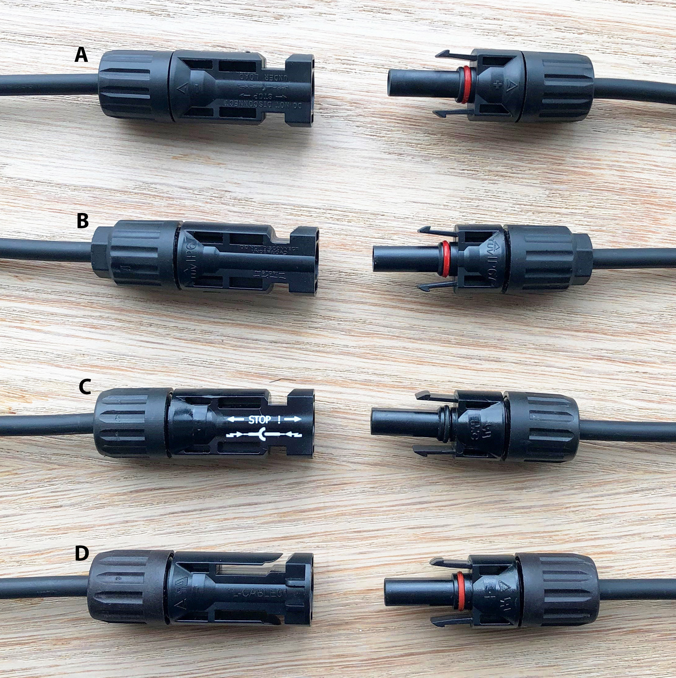
DC Connector > Failure Mode > Cross-mated Connectors

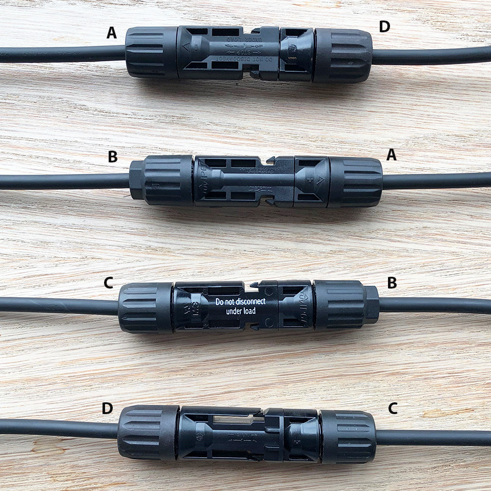
Cross mated MC4 and "MC4 compatible" connectors

Another failure mode is connection faults arising from the cross-mating of dissimilar DC connectors from different manufacturers.  This is forbidden in principle in both the UK (by MIS3002) and Netherlands (by NEN1010), but in practice it is difficult to comply with, and almost impossible to police - read my earlier blog on the fire risks from cross-mating DC connectors.  


Since 2019 Viridian Solar has only fitted genuine Staubli MC4 connectors to its Clearline fusion solar panels, guaranteeing compatibility and enabling installers to easily purchase matching connectors locally for extension cables.  While the solar industry awaits the development of a global standard for DC solar connectors that would ensure inter-operability of different plugs and sockets, I would urge that panel manufacturers at the very least should declare the manufacturer of the DC connector on the solar panel nameplate to allow installers to comply with local regulations the prohibit the mixing of connectors from different manufacturers.


DC Connector > Failure Mode > Poor Crimped Joint Quality


A third failure mode occurs where cables need to be added to the circuit to bridge longer distances, such as between panel rows or from the panels to the inverter.  The solar installer needs to make a crimp joint on site to join a DC connector to a cable of the right length.

Tests published by Staubli shows the importance of correct crimping.  It is possible to make a crimp with a set of pliers instead of using the proper tools, which could easily happen given the cost differential and convenience of using pliers instead.  However,  the pull-out resistance and resistance to corrosion are both severely compromised.  Either could lead to arcing in the connector, in turn leading to a fire.

Again, installer training and competence is the best way to avoid this risk.


DC Connector > Risk Mitigation > Enclosure


DC Connector Enclosure Device

If you can't eliminate or substitute a component, the next step in the risk reduction hierarchy is to apply a control to isolate the hazard.  An example of this approach is the new ArcBox solar connector enclosure.  A clamshell containment device that snaps around the DC connector and, should an electric arc form inside a DC connector, stops it spreading to combustible material around the connector and preventing the failure developing into a fire.


General > Risk Mitigation > Arc Fault Circuit Interrupter (AFCI)

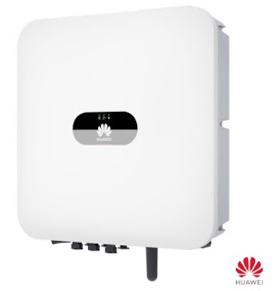
Huawei inverter with AFCI 


Inverter manufacturers are now offering Arc Fault Circuit Interruption (AFCI) as a product feature.  This approach continuously monitors the frequency of electrical noise on the DC current or voltage signal, disconnecting the circuit within 2.5 seconds (IEC 63027) whenever noise that is characteristic of an arc is detected.  The system resets after a period, with the period before reset increasing each time an arc is detected until a manual reset is required if the device resets more than 5 times in 24 hours.  

One challenge with this approach is that electrical noise from naturally occurring sources may be difficult to distinguish from an arc - which may cause nuisance tripping.


General > Risk Mitigation > Eliminating Combustible Materials


Another control measure to reduce the risk an electrical arc fault develops into a serious fire is to ensure that combustible material is not installed or allowed to accumulate around the solar panels.

Birds and small mammals find the space behind a solar panel an attractive place to build nests.  Wind-blown debris can also accumulate behind some solar panel systems.  Some manufacturers recognize the risk and instructions require users to go on the roof and clean it out.  Better to specify a solar system that does not have openings that allow animals, birds or wind blown ‘foreign materials’ access to the area behind the panel.

Some in-roof solar mounting systems are comprised of sheets or trays of plastic cladding placed behind the solar panels to provide a waterproofing layer.  This obviously adds to the 'fuel' available to any fire that might start, and a risk mitigation measure would be to avoid mounting systems that add combustible materials to the installation in this way. 


In Conclusion

Solar is a safe technology, but there are many ways to make it even safer - and this will become more and more necessary as the number of solar installations increases in coming years.

Some of these risk mitigation opportunities add cost to the installation, others are costless and require only more diligence in installation or simple specification choices that can reduce the risk of a fault condition progressing to become a full-blown fire.  It is likely that both and all forms of risk reduction will be necessary to meet the demands of customers and insurers.  If the industry doesn't act of its own accord, it may have change forced upon it.


Friday 20 May 2022

Owner Occupiers - Government's Final Frontier for Energy Efficient Buildings

Dutch Householders Must Now Include Renewables When Making Major Home Improvements
Image (C) Viridian Solar

UK energy efficiency laws have been made for new homes and new commercial buildings, for houses owned by private landlords (in England) and those managed by Social Housing  Providers (in Scotland), but the biggest part of the building stock has so far sailed on without interference from lawmakers in the UK - those owned by private individuals.

Unlike owner-occupiers; house-building companies, local authorities and social landlords don't get to cast a vote in a general election, making them easier targets for potentially costly or unpopular new laws.  When David Cameron's celebrated coalition government put forward an idea to require improvements to energy efficiency alongside home renovations called 'Consequential Improvements' in 2012 it survived only a few days after being  dubbed the 'Conservatory Tax' by the Daily Mail.  

See also this post from 2013 on the death of the Consequential Improvements idea.

If you are doing building works on your home, the current building regulations apply to the new bits you build, so any new walls and roofs would be insulated to modern levels.  The idea of the Consequential Improvements proposals was that (subject to the work exceeding a threshold of size) you should also have an obligation to make energy efficiency improvements to other parts of the building (for example topping up loft insulation or installing an efficient boiler or solar panels).

Looked at from the perspective of today, with occupants of inefficient housing most exposed to rampant energy cost inflation it certainly looks like a missed opportunity.  Hooray for the Daily Mail - a genuine force for good and yet again, as so often, on the right side of history!  Householders were freed from having to pay "hundreds of pounds extra on energy efficiency when they build an extension or fit a new boiler" in return for the privilege of paying thousands of pounds extra every year for soaring energy bills.


10 Years Later, in The Netherlands

Across the North Sea, the Netherlands government has brought in something that looks uncannily like the UK proposals of 10 years ago.

From February 1, 2022 an update to the "Bouwbesluit 2012" (Building Decree) regulations  place a requirement on renovation projects in Netherlands to include renewable energy.

Only renovation projects that meet both of the following requirements fall under the new rules:

 (a) more than 25% of the external envelope (ground floor, walls and roof) of the building is changed, and

(b) a heating or cooling system is part of the renovation - for example changing a central heating boiler, or replacing a third or more of the radiators.

The law applies to both housing and non-domestic properties. 

If a renovation falls under the new rules then renewable energy must be installed.  The amount you should install is derived from a formula which specifies the amount of renewable energy per year the system should yield:

30 x Aroof / Ag  kWh/m2.yr  (subject to a maximum of 30kWh/m2.yr)

Aroof is the roof area and Ag the "Gebruiksoppervlak" (usable floor area) as defined in NTA 8800:2020+A1:2020

So taking the example of a house with 100m2 of total usable floor area split in the typical Dutch style over ground floor and first floor in the roof , say 60 m2 to ground and 40 m2 to first floors together with a roof pitch of 45 degrees.  By trigonometry, the roof area is 1.41 x the ground floor area - 84.6 m2.  The calculated annual renewable energy is 30 x 84.6/100 = 25.4 kWh/m2.yr, or 2,540kWh/year in total when multiplied by the 100m2 total floor area.

This quantity of renewable energy production is very easily met with solar - around 3kWp would do it.

Certain exemptions are possible.  If you can show that the measures to meet the requirement would have a payback longer than 10 years, then you can install a smaller amount that does pay back in under this time.  Buildings with an occupancy type with very low energy use are exempt.  Finally buildings with special circumstances such as monumental buildings can be exempt from the requirement altogether if their protected status prevents the installation of measures.

The building owner has a choice of options to meet the requirement - for example joining a heat network, solar PV or installing a heat pump.  For solar PV, the Dutch government has helpfully provided a solar calculator to determine how much Solar PV is needed, based on NTA 8800:2020+A1:2020, a standard providing a method for the determination of energy use in buildings.   The solar calculation is from Chapter 16 of NTA 8800 and takes the installation details into account (orientation, shading, etc…).

In most cases the requirement for solar PV works out at between 15 and 20% of the roof surface area.  For example: Using  Clearline fusion PV16-335-G1 roof integrated solar panels (which are classed as ‘moderately ventilated’ because the air gap behind the panels exceeds 100mm); on a South facing orientation; on a 35⁰ pitched non-shaded roof; on a building of 100m2, you would need 8 panels to meet the requirement.

From the point of view of the solar industry, which offers a simple, proven and low-cost way to comply with the renewable requirement, this is a welcome change that ought to result in a good deal more solar PV on homes in the Netherlands.  

Looking at the requirements more critically through the lens of energy efficiency it does strike me a somewhat one-dimensional.  Why not require changes that improve fabric efficiency - thermal insulation and draft-proofing as well?  Perhaps the Netherlands building stock is more air tight and better insulated than that in the UK, but I'd be very surprised if there isn't lots of stock that could also benefit from improvements in this area.  The 'fabric first' brigade in NL must be looking for their pitchforks and burning torches.

The new renewables obligation in the Dutch Bouwbesluit 2012 does have the advantage of being very simple to calculate, implement and install.  Perhaps it's an example of pragmatic legislation that doesn't letting the perfect become the enemy of the good?  Just getting on and doing something to make a difference!  Is there a Dutch equivalent of the Daily Mail?  Where was it when it was needed to stamp all over a progressive and practical idea for improving the world?


Friday 29 April 2022

Cross-mating of Solar DC Connectors and Fire Safety


Imagine you've just got home with this season's must-have kitchen appliance - perhaps the Nostalgia Pop-up Hot Dog Toaster ("why boil water when you can  toast?")

You can almost taste those delicious toasted hot dogs as you unpack your new purchase but you notice a warning label attached to its power cable:  "Do not cross-mate this plug with sockets of another manufacturer's brand."  When you check the plug on your Pop-up Hot Dog Toaster and the power socket in your kitchen  you can see no identifying markings to tell you which company made either of them.  Disappointed, you reach for a pan to put some water on to boil...

This is the farcical situation in which the solar industry finds itself today.

An industry estimated to be worth $180bn in sales, producing 500 million panels a year cannot agree on a standard for the connectors that are used to wire up a solar installation.

What's more - many solar installers are going about their business blissfully unaware of regulations that mean it is not permitted to connect DC connectors from different manufacturers together.

About Solar Connectors


DC Solar Connector pairs from a selection of manufacturers
(A) Ningbo Yuling  (B) Shenzen Leader Technology   (C) Staubli International   (D) Tonglin


Solar panels come with a plug and socket attached to flying leads that enable one panel to be connected to the next to create the electrical circuit.  This connector is commonly referred to as an MC4, but in many cases it cannot strictly be called this (of which more later).  

MC4 style plugs and sockets are enclosed by plastic shells.  One of the shells has two plastic fingers that pop outward to lock the two together as they are pushed together by hand.  So long as the two connectors are pushed fully together, they cannot be accidentally disconnected if the cables are pulled.  

The "4" in the name corresponds to the 4mm diameter contact pin in the plug and the "MC" stands for Multi Contact, a US manufacturing company that invented this design of connector, now owned by Staubli International AG, a multinational manufacturer of electrical connectors, fluid connectors and robotics.

So only connectors made by Staubli can really be called MC4.  However since its invention, Staubli has watched on as low-cost manufacturers have brought out copies of the MC4, or at least copies that match closely enough that a plug from one manufacturer and socket from another can be physically pushed together.  These connectors are often referred to (not least by the companies that make them) as "MC4 Compatible", which of course makes it sound like it should be fine to use them interchangeably.   

And there are dozens of these other manufacturers making these MC-4 compatible connectors. Most solar PV panel manufacturers will have a number of different suppliers listed on their technical construction file so they can choose between them based on price and availability.  Some of the larger PV module manufacturers even have their own-brand in-house DC connectors just for their own panels.

MC-4 "Compatible"


Prohibited in some legal jurisdictions - but how would you ever spot it?


But who decides whether these connectors are truly "compatible" with one another?  

The design and dimensions of domestic plugs and sockets are clearly defined in technical standards (for example CEE-7 standards for plugs used in Europe and BS1363 -first published in 1947- in the UK).  Any plug or socket can be tested against the standard and declared to meet it by an independent test laboratory.  All plugs and sockets that meet the standard are safely inter-operable.  

By contrast, there is no such standard for DC solar connectors.  Connector manufacturers can go to a test laboratory such as TUV and get certification for their product, but for the most part the only testing undertaken is that their own plug and socket work together.  With so many different manufacturers, it is impractical to have to test every plug with every other manufacturers socket.  

Even when a manufacturer tests its connectors with those of another manufacturer - who is to say that the design will remain compatible since the other manufacturer could make changes to its design in the meantime and has no obligation to tell the first manufacturer.

Staubli has published in-house research on cross-mated connectors (see page 22 of this report) and (while recognising the researchers are commercially conflicted) the reported results do make the case that it is not safe to mix connectors from different manufacturers.  After subjecting the cross-mated connections to 2,000 temperature cycles and 1,000 hours of damp heat the connector resistance increased leading to connectors overheating, which in turn can result in a mechanical failure and a DC electric arc leading to a fire. 


Concerns about fire safety and the interoperability of DC connectors from different manufacturers has led many national solar installation standards bodies to either prohibit or advise against the mixing of plug and socket from different manufacturers.  


5.9 Where plugs and sockets are mated together in any part of the PV array circuit they shall be of the same model and from the same manufacturer.


In the UK, MIS3002 - the MCS installer standard for solar PV adopts the IET Code of Practice in full.  What this means, and it seems that many people in the solar industry are unware of it, is that for MCS compliant installations in the UK cross-mated connections are prohibited.

In the Netherlands, where there has been a high level of concern at fires starting in solar installations, there is a similar requirement.  NEN1010 is the applicable standard for low voltage electrical installations.  For solar DC wiring it has the following to say:

712.526.1   The combination of plugs and sockets from different manufacturers is only permitted if both manufacturers endorse the compatibility of the plug-socket.

NOTE 1 It is recommended that each plug and receptacle combination be made by the same manufacturer.

So while stopping short of the black and white position taken in the IET guide, the requirement that both manufacturers endorse the inter-compatibility of their products effectively does the same thing if such an undertaking is not available (which it commonly is not). 

Theory and Practice


The standards may be good in theory, but practical difficulties emerge as soon as you get on site and try to make a solar installation that complies with their requirements.  As mentioned before, solar panel manufacturers might make one batch with one manufacturer's connectors and then switch over for the next batch to another manufacturer that has given a better price.  If the panels an installer buys crosses over the batch then it will include panels with mixed connectors.

To make things more difficult for the installer, the connectors all look very similar and have few distinguishing features and marks.  

In addition to joining each solar panel to its neighbour in the row, the installer must make electrical connections across distances longer than the leads that come with the solar panel.  At the very least this would include cables connecting the first and last panels back to the electrical inverter but might also include cables to join spaced-apart arrays together.  These cables are commonly made to the right length on site by the installer, with cable and connector crimped together using hand tools (the additional fire risks posed by hand-crimped DC connectors is the subject of an upcoming blog).  


Connectors at either end of the string of solar panels are more likely to be cross mated as the long cable back to the inverter is made by hand on site.


To comply with the regulations while preparing these extension cables the installer must either: 

(a) identify the brand of connectors on the panels and purchase the same connectors locally - but they are not easy to identify and often not available to buy locally, or 

(b) snip off the connector from the panel cable and replace it with a locally bought one that matches the connector to be used on the extension cable.  In this case we are replacing a factory-made crimp with a  hand crimped joint and possibly invalidating the panel manufacturer's warranty by modifying the product.  

To help installers meet these challenging requirements, some panel manufacturers will not mix connector manufacturers and guarantee that their panels only come with genuine Staubli MC4 connectors which are readily sourced locally by installers.  

These manufacturers remain in the minority and most solar panel manufacturers are producing modules with a variety of different connectors, many of which cannot be sourced locally.  For these, solar installers find themselves between a rock and a hard place if they are to follow the regulations.


Conclusion


This is an international problem and the international standards bodies hold the key to solving it.  The International Electrotechnical Commission (IEC) Technical Committee 82 has apparently been discussing whether to create a specification for solar connectors for many years, but there is no sign of progress in this area.  

Solar installers and their customers find themselves caught between regulators creating installation standards that are almost impossible to meet in practice and an IEC committee packed with industry experts drawn from businesses that appear to have a commercial incentive to avoid the standardisation that would resolve the problem.

The Type 2 connector for Electric Vehicle (EV) charging was originally developed by a commercial company - Mennekes as a  proprietary standard.  It has been adopted as the standard for EV chargers and the specification is now described in IEC 62196, allowing manufacturers to make inter-operable products for the safety and convenience of customers.  This demonstrates that it is possible to put aside narrow self-interest for the good of the whole industry and more quickly advance the transition to clean energy.

It is shameful that the representatives of the solar industry at IEC have not managed to do the same.
Even if the IEC committee decided to act today, given the time standards take to develop, we would be many years away from seeing compatible connectors on the market.  

In the meantime many solar installers are unknowingly making non-compliant installations and could find themselves liable if the worst were to happen.  A good initial step that could be taken quickly would be for solar panel manufacturers to unilaterally declare on their solar panel rating plate which make and model of connector it is fitted with and, if the type is not widely available in the after-market, to supply matching connectors alongside the module.  This would enable installers to comply with standards.


Friday 18 March 2022

How Safe is Solar PV?

 Putting the Numbers in Perspective


Comparing the fire risk from solar PV with that from common electrical appliances
Comparing the fire risk from solar PV with that from common household appliances


Recent research has advanced our understanding of the risk of solar PV fires.  The Building Research Establishment (BRE) and the Netherlands Organisation for Applied Scientific Research (TNO) published reports of their investigations of fire incidents involving solar PV installations in the UK and Netherlands respectively.

In this blog we take a look at the numbers and try to put them in perspective by comparing the findings from the reports with statistics for fires started by household appliances.


Fire and Solar PV Systems – Investigations and Evidence, Coonick et al, BRE National Solar Centre, 11th May 2018 (link)

Researchers from the BRE National Solar Centre investigated 80 fires in the UK that involved solar PV systems in some way, either because it was a potential source of the fire or because it was involved in a fire that started elsewhere. 

The solar PV system was found to be the source of the fire in 56 of the incidents.   Of these 22 were classified as serious fires (those that were difficult to extinguish and spread beyond the point of origination), with the remainder being classified as either localized or ‘thermal events’ (smoking, overheating).  The investigation looked at incidents that were both historical (33 that happened before the project start date of July 2015) and live (47 that occurred between July 2015 and February 2018).

It would be misleading to compare the number of fires caused by solar with the number of fires caused by other electrical appliances - because there are so many more of these.  To make the comparison fair we should take into account the number in operation.  I'll be using the number of fires each year per million systems in operation as the benchmark figure.

Taking the overall proportion of fires where the PV system was found to be the source of the fire (56 out of 80) and applying this figure to the 47 live incidents collected over the 30-month project length gives a rate of 13.2 solar PV fires/year.  

In January 2017 – half way through the study, the cumulative number of PV installations in the UK was 904,033 systems.

So our rate of 13.2 fires in 0.904m systems translates into 14.6 fires per million operational solar PV installations per year.


Brandincidenten met fotovoltaïsche (PV) systemen in Nederland. Een inventarisatie.  Bende EE & Dekker NJJ, TNO, 13th March 2019 (link)

The TNO researchers identified 28 incidents in the period 2015-2018 categorised into both residential properties and business (which includes both commercial buildings and ground arrays).  21 of the fire incidents occurred in 2018, and 15 of these were on residential properties.

The Central Bureau of Statistics (CBS) publishes data on the number of solar installations in the Netherlands.  At the end of 2018 there were 720,522 domestic installations, and 67,313 commercial installations.

The calculated fire rate for solar PV systems on domestic properties based on 2018 is therefore 15 in 720,522  or 20.8 fires per year per million systems in operation.


Comparison with Common Electrical Appliances

Data published by the UK Home Office on incidents attended by the Fire and Rescue Service in England breaks out the causes of fires, and from this we can get numbers that allow us to compare with the figures for solar PV.

Workings are detailed below, but what can be seen from the figures is that solar PV systems safety compares very favourably with that for electrical appliances that we wouldn't think twice about having in our homes.

It may be highly reassuring to say that a PV solar system is safer than a toaster or tumble dryer, but that doesn't mean that the solar industry should complacently sit back and do nothing.  Both reports highlighted common faults that can lead to fires.  In my next blog I'll be looking into these to ask what steps the industry can and should take to improve the safety of solar systems further.


Sources and workings on figures for electrical appliances 

In 2020 there were 27,292,000 UK households.  England represents 84% of UK population.  So let's assume 22,925,000 households in England.

98% of UK households own a washing machine, giving a number in use in England of 22.47m

91% own a toaster, giving 20.86m in use in England

58% own a tumble dryer, 13.30m in use

49% own a dishwasher, 11.23m in use


The Domestic appliance fires dataset was accessed from this UK government web page.  The average number of fires each year in England from 2010 to 2020 was used.  This figure is divided by the number of appliances in use (in millions) to get a rate per year per million appliances in use for comparison with the solar PV figures.

Friday 11 March 2022

The Electric Arc and DC Solar Systems

If you cut a wire in an electrical circuit, current will stop flowing because the air in the gap is a very good electrical insulator so electrons cannot travel across it.


A electric field is formed between the positive and negative sides of the gap (which are called the electrodes), represented by the red field lines in the diagram below.


If you increase the voltage between the two electrodes, or narrow the distance between them, the electric field across the gap increases in strength.


If the electric field is strong enough, it will pluck electrons away atoms in the gas molecules in the field, causing the gas molecules to split into positive ions and negative electrons.  Both electrons and positive ions are attracted towards the oppositely charged electrode, so they accelerate off in that direction.  A current is now flowing in the circuit again.


But as the ions and electrons move in the field they can collide with gas molecules.  The energy from the collisions is seen as a temperature increase.


More electrons moving between the electrodes means there are more collisions with the uncharged gas molecules.  A chain reaction (or avalanche effect) occurs with more collisions leading to more charged particles and more charged particles leading in turn to more collisions.  We now have a high temperature plasma between the electrodes and this is a far better conductor of electrical current than air because of the greater number of charged particles available to move across the gap.


Temperatures are now so high in the gap that an intense white light is given off and the conductor material  may be vaporised away - an electric arc has formed.  

Even though the loss of electrode surfaces means the gap width increases the plasma's higher conductivity means that the current continues to flow.  A much lower voltage is needed to maintain an arc than is required to start it in the first place, an effect is well know in welding where 'striking an arc' refers to tapping the welding stick on the work piece and pulling it away.  The arc forms when the gap is narrow but is maintained as the stick is moved away to the working distance.

Arcs can be useful in applications such as welding, but undesired arcs are a potential source of fires with  the high temperatures in electric arcs easily capable of setting alight combustible material nearby.  Great attention is paid in electrical installations to avoiding arcs forming in the first place.

DC Solar Systems

There are two reasons why arcing is a particularly relevant consideration for solar systems.  

Firstly the voltages in solar systems can be very high compared to the Alternating Current (AC) supplied from the grid, and as we've seen the higher the voltage, the stronger the electrical field across a gap and the more likely is is that an arc will form.

In European countries AC electricity is supplied at 230-240V for domestic and small commercial buildings.  The most common electrical arrangement for the solar panels in a solar PV installation is to connect the panels (which might be 35V per 340Wp module) in a series string with the voltage increasing with each panel added.  For a 4kWp, 12 panel installation the voltage reaches 420V.  In larger commercial and utility scale installations voltages up to 1,000V or 1,500V are commonplace. 

Secondly, an AC electric arc is more likely to self-extinguish once formed because the voltage goes through zero volts 100-120 times a second (50 or 60Hz supply) and each time this happens the arc needs to re-establish.  Because the field strength required to start the arc is much higher than that needed to keep one going any increase in the arc length due to electrode erosion will mean that the arc will not re-establish.  By contrast the DC voltage in a solar PV wiring system is constant and the gap will need to open up much further before the arc is extinguished (this is why most forms of arc welding use DC current).

These factors mean that greater attention must be paid to arc risks in solar PV systems.  Despite this the safety of solar PV systems is very high, and this will be the topic of my next blog.


Tuesday 22 February 2022

How Progressive Building Regulations Made Scotland a Solar Powerhouse


Statistics recently published by the Microgeneration Certification Scheme (MCS) show how much solar PV different regions in the UK installed in 2021.  Scotland really stood out from the pack, with more than 25% of all installations.  However, because the graphic only showed the number of installations, and didn't take into account the population of each region it doesn't really do justice to the wide differences between different parts of the UK.

The Solarblogger has restated the figures above as the number of installations in 2021 per 100,000 of population in the region (the blue boxes).  

On this measure you can see that Scotland is installing two times more solar per head of population than the next nearest UK region (the South West) and more than three times the national average.

Compared to laggards like Northern Ireland and London, Scotland is installing more than ten times more solar PV installations per capita.  What is behind this incredible performance?


In 2015, Scotland brought in new building regulations that required housebuilders to construct homes that were significantly more energy efficient than those being built in the rest of the UK.  A year later George Osborne killed off the Zero Carbon Homes policy and developers in England have been building to performance levels largely unchanged from 2010 ever since.

The preferred option of housebuilders in Scotland has been to meet the regulations with a combination of improved thermal insulation and airtightness, combined with a solar PV on the roof (or to be more accurate a solar PV installation in the roof).  As housing developments started under previous regulations came to an end and new projects started up that needed to meet the new regulations, the proportion of homes built with solar rose from around 10% before the regulations to nearly 70% in 2020.


According to an analysis of the EPC database in Scotland by Kevin McCann at Solar Energy UK, of the 15,447 EPCs registered for new homes in Scotland in 2020, 10,324 listed solar PV as an energy efficiency measure.

So of the 16,437 Scottish solar PV installations registered with MCS in 2021, it is likely that at least 10,324 were new homes, which would leave 6,113 that were retro-fitted to existing buildings. 

Taking this retrofit figure per head of population alone would give Scotland a score of 112 installations per 100,000 people - still impressive but it is clear that Scotland's stand out performance in solar PV installation has been driven by the building regulations for new homes.

In 2021 it is possible that there was an even higher figure for solar on new homes than that we have for 2020.   Lockdowns paralysed the construction industry for a good part of 2020, and 16,000 new homes is some way behind the long run average of around 20,000.  So the contribution to Scotland's performance from Building Regulations is likely to be higher still.

The good news is that regulations for England and Wales will soon exceed those in Scotland, with new regulations in England coming into force this June.  When that happens we should see solar PV installations per capita start to close the gap with those in Scotland.